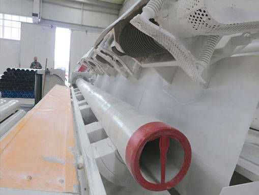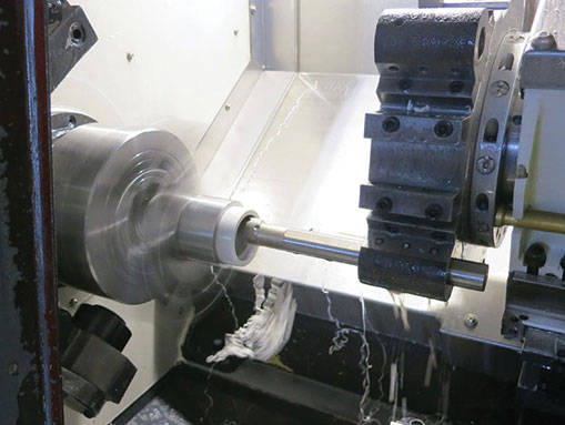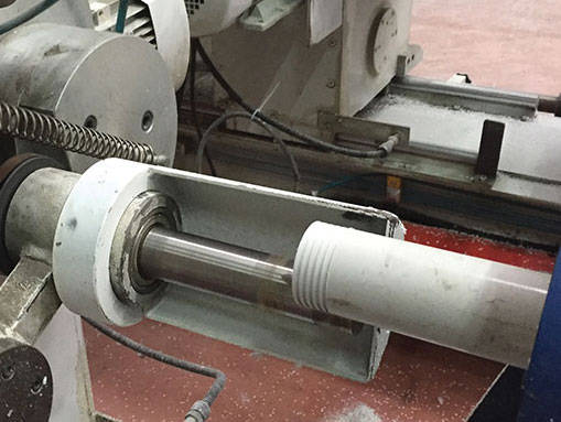
Square threads specially designed for DCP Column Pipes and sleeves are made on the latest generation threading machines. By thickening the pipe ends with special production methods, the safe wall thickness value of the pipe is preserved after threading. Special adhesive is used to fix the sleeve to the pipe. Sealing is ensured by the o-ring seals used between the pipe and the sleeve. The tightening torque applied during the well installation and the pipe head parts come into contact with each other, creating a pre-stress on the square threads. This pre-stress prevents self-dissolving in the teeth.
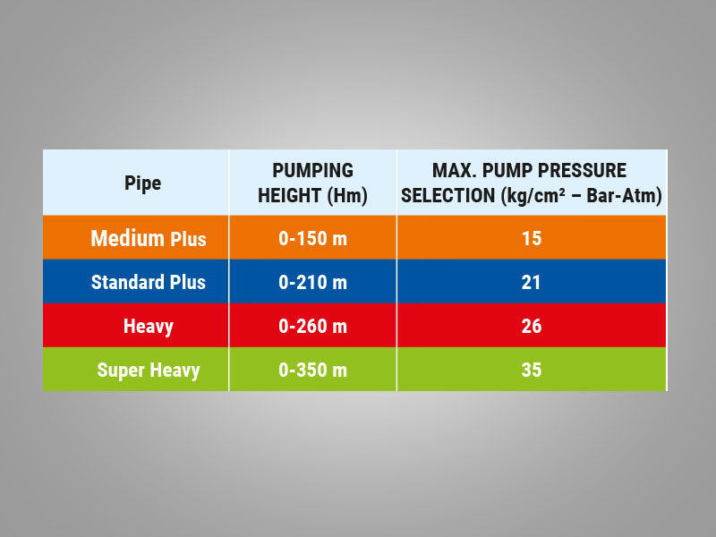
The design of the DCP Column Pipes has been made according to the safe head (Hm) of the pumps determined by taking into account all the pressure factors in the system. Even if DCP Column Pipes will be used at lower depths, they should not be selected as lower than the maximum pressure value of the pump.
Max. pressure of pump must not exceed the allowable hydrostatic pressure of the pipe. The laying depths of the pipes should be calculated according to the formula given below. All units are meters.
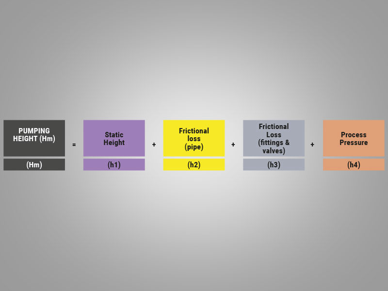
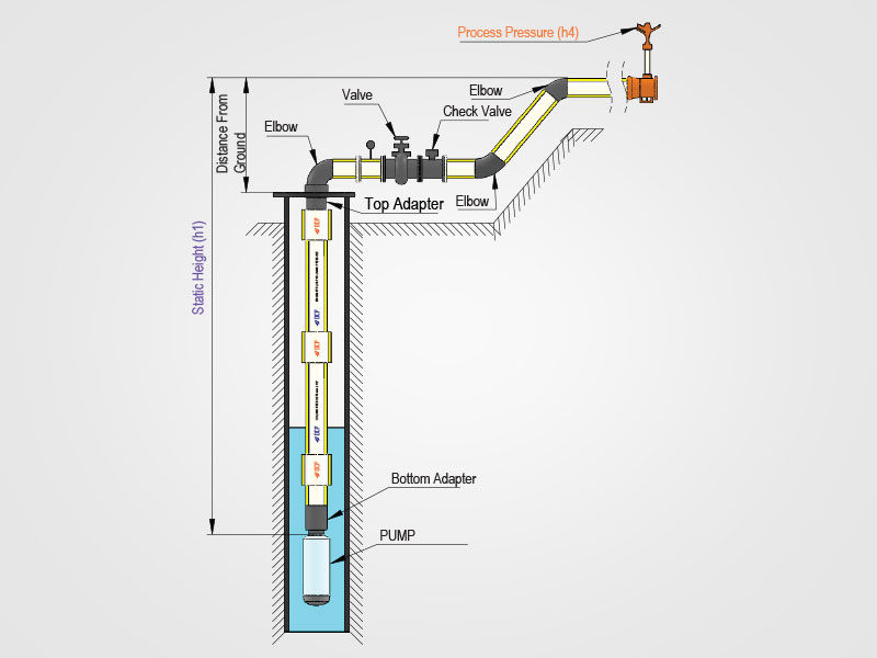
Pump(ing) Height (Hm) : Static height in the pipeline, frictional losses and the total pressure acting on the pipe as a result of the process pressure.
The general principle in Height-Pressure conversion is 10 mSS = 1 kg/cm2.
Static Height (h1): It is the height difference between the lowest and highest level of the pipeline.
Friction Loss in Pipe (h2) :
It is the friction loss that occurs along the pipeline. Appropriate pipe diameter should be selected to minimize loss. Friction losses in the pipe can also be calculated with the Hazen-Williams formula.
Pm = 6.05x [(Qm 1,85)/(C1,85 dm4,87)] x105
Pm = Frictional resistance per unit length of pipe (bar/m)
Qm = flow rate (lt/min)
C = Friction Loss Coefficient (PVC = 150 )
dm = pipe inner diameter (mm)
Friction Loss in Fittings & Valve (h3):
It is the pressure loss caused by elements such as fittings and valves in the system. In practice, 10% (h1+h2) is taken. For more accurate calculations, equivalent straight pipe lengths corresponding to the same resistance loss of valves and fittings should be used. Manufacturers' catalogs can be used.
Process Pressure (h4) : It is the operating pressure required at the end of the pipeline. (30 m (3 bar) in irrigation systems, 10 m (1 bar) in residences, 0m (0 bar) in free flow to pools). Note: Normal use temperature is 25°C. 10% performance loss will be taken into account for every 5 °C increasing temperature. The maximum usage temperature is 50 °C. It works with 50% performance at 50 °C.